


(4) Sealing theory
(a) Basic theoryAs the sealing theory of gland packing, studies by D. F. Denny and D. E. Tumbull are available.
D. F. Denny expressed the equilibrium state of internal stress as depicted in Fig. 1.2.1 when the compressive stress σG was applied to the packing which was sandwiched between two metallic walls as shown in Fig. 1.2.2.
Fig.1.2.1 Packing Sandwiched between Metallic Walls
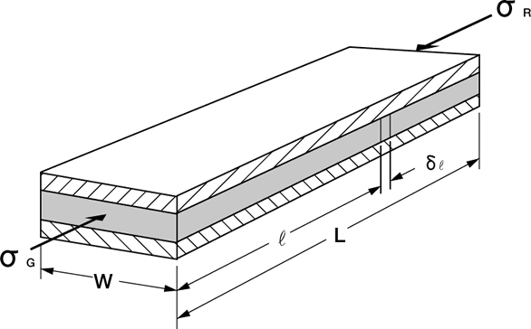
Fig.1.2.2 Equilibrium State of Internal Stress of Packing
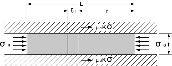
Within the packing, a balance of stress is achieved as shown in Fig. 1.2.2, so that σ+δσ and the corresponding reaction forces σ and μKσ come to equilibrium at a given point of packing. At the same time, a force of Kσ is produced on the wall surfaces. Here K is a factor which is specific to the packing, normally ranging from 0.6 to 1.0.
If this is expressed by means of formulas;
![]()
(Formula (2) is integrated to provide P=PG when r=0. This can be substituted to obtain formula (3) .
![]()
This is a formula representing the stress distribution within the stuffing box when the tightening stressσG is applied.
Next, an attempt will be made to obtain a formula for calculating the internal stress that occurs when the packing is actually stuffed into the stuffing box.
Fig.1.2.3 Stress Distribution of Packing within the Stuffing Box
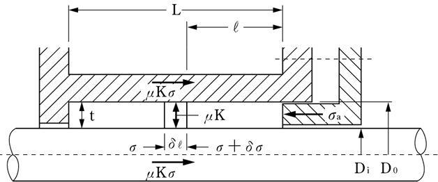
Take Fig.1.2.3 and assume the packing has a square shape of cross section andμ1=μ2=μ, then
![]() is established. Substitute this into formula (3) to provide:
is established. Substitute this into formula (3) to provide:
![]()
Now substitute 0.8 for C to derive;
From formulas (4) and (7);
The compressive stress at a given point within the stuffing box can be found by substituting N and μK values into formula (8).
For a practical measurement, μ and K values will take a form of μK, which represents the shaft sliding factor of packing. Table 1.2.7 shows the μK values for typical types of packing.
Table 1.2.7 μK Values for Typical Types of Packing
| Item & Packing type | μK value (dimensionless) | Typical VALQUA No. |
|
| At starting | At sliding | ||
| Lubricated VALFLON-impregnated carbon fiber packing | 0.02~0.03 | 0.01~0.02 | 6232、6262、6399L |
| VALFLON-impregnated special fiber packing | 0.03~0.04 | 0.02~0.03 | 8137 |
| VALFLON fiber packing | 0.03~0.04 | 0.02~0.03 | 7233 7232 |
| Expanded graphite packing | 0.07~0.09 | 0.04~0.06 | VF-10、VF-20 |
| Low torque-treated expanded graphite packing | 0.03~0.05 | 0.03~0.04 | VFC-25、VF-20LF |
| PTFE-clad expanded graphite packing | 0.02~0.03 | 0.02~0.03 | VFT-22 |
Also, if the shaft is activated while maintaining σG after installing and tightening the packing, the resultant change in the tightening stress can be determined in the following manner:
Assume that the shaft is moved to the left in Fig.1.2.3. and the tightening force of packing transferred by that motion is higher than μKσ by 30%. Then;
![]()
If Do=32 and Di=20 are assumed for a standard size of packing, then;
(Do−0.3Di) / (Do+Di)=0.5
![]()
From this, the following are generalized;
For not activating the shaft after tightening the packing:
![]()
For activating the shaft after tightening he packing:
![]()
(i) Leakage
The leakage rate Q is roughly expressed by;
![]()
where:
r' : Packing length taken from the inner depth of the stuffing box.
![]() :Gradient of the fluid pressure acting on the shaft surface.
:Gradient of the fluid pressure acting on the shaft surface.
According to the studies by Denny et al., the sealing property is governed by PG alone and the leakage rate Q is inversely proportional to PG2 and proportional to Pf on condition that the fluid pressure Pf is low enough not to affect the tightening pressure PG.
If Pf is very high, on the other hand, the sealing action becomes automatic, so sealing takes place only at a portion of about 10% near the packing gland and the other portions are involved in neither of sealing or torque. Therefore, the number of rings installed has nothing to do with the sealing action.
(ii) Shaft resistance
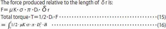
Hence, formula (3) can be substituted into formula (16) to derive:

Roughly speaking, the following formula are thus established:

(b) Estimation of leakage rates in pump & equipment applications
When using gland packing as a dynamic seal, an estimate of the leakage rate is calculated in the following manner.
The target fluid for estimation is an incompressible viscous fluid, and leakage in a laminar flow state is presumed.
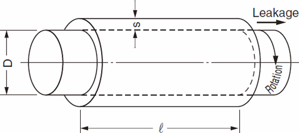
(i) For rotating applications
For a leak flow that runs in a very narrow gap between a rotating cylinder and a stationary shaft or between a stationary cylinder and a rotating shaft, the following relational expression is available on condition that the gap is defined as s:

D: Shaft diameter, ΔP: Differential pressure (P1-P2), P1: Fluid pressure
P2: Atmospheric pressure (normal),η: Fluid viscosity, r: Seal length (Length of packing when installed and tightened)
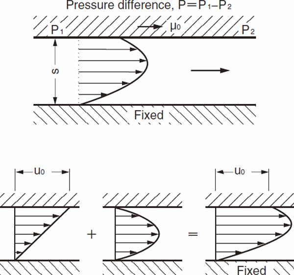
(ii) For reciprocating motion applications
A wall motion at the right angle to the direction of leakage does not affect the leakage in a laminar flow state, but a wall motion in the direction of leakage does. In this case, the sum of the pulling force of the moving wall and the leakage flow between the moving and fixed walls due to a pressure difference is applicable, and the leakage rate per unit width, Q, can be expressed by;

If the gap s is assumed to be a cylindrical one in a diametrical direction, the leakage rate can be derived by multiplying the value of Q in formula (23) by the circumferential length πD as follows:


However, if the direction in which the wall moves is opposite to the direction in which the pressure acts, then:

As a result, Q < 0, Q = 0, or Q > 0 could be established.
Cited literature
1)Denny, D.F.・Turnbull, D.E., SEALING CHARACTERISTICS OF STUFFING-BOX SEALS FOR ROTATING SHAFTS, Proc Instn Mech Engrs, Vol 174 No.6 P271, 1960
