


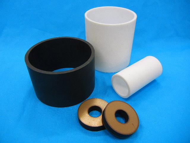
VALFLON ® Bearing
- VALQUA No.
- 7500
- Product name
- VALFLON ® Bearing
- Features 1
- This is a processed product in which a PTFE containing filler is cut into a designated shape and made into a bearing and skid.
■ Applications
■ Features
■ Characteristics
Friction characteristics
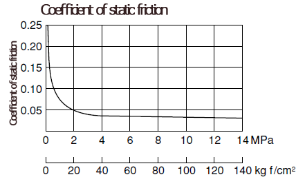
(A) Coefficient of static friction: This is high when the load is small, and it gets lower in correlation to the increase in load.
Generally, it is between 0.04 and 0.16 (except when the load is extremely small)
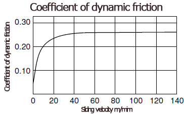
(B) Coefficient of dynamic friction: This is small at low velocity, and it gets larger in correlation to an increase in speed.
Generally, it is between 0.12 and 0.19
(C) It can be said that the temperature has no substantial impact when between room temperature and 327℃ (melting point of PTFE), and the effect will rapidly increase when passing the melting point.
(D) The relationship between the above-mentioned (A) to (C) will also be maintained in PTFE containing filler, but the coefficient of friction will slightly increase.
[Note] In IV Materials 1.1(8) we indicated the coefficient of static and dynamic friction of PTFE as well as PTFE containing various fillers, but as described earlier the coefficient will vary depending on the operating conditions.
As such, these values are only indicative of examples under limited conditions, and they are shown in the sense of providing a relative comparison.
Therefore, in applications that heavily emphasize the absolute value of the coefficient of friction, it is desirable to perform actual measurements under practical conditions with a dummy.
PV Value
The PV value is a value derived from load P (MPa) x velocity V (m/s), and it is related to the amount of heat generated from the bearing surface. If the heat generated cannot be diffused and is instead reserved, it will reach the melting point of PTFE and quickly be destroyed, so the PV value gives a general indicator of the operating limits.
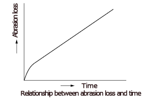
Figure 5.1.19 shows the relationship between PV value and amount of wear.
A proportional relation is more or less retained between the PV value and amount of wear until the limiting PV value, but it will no longer be able to diffuse the generated heat when the limiting PV value is reached, the temperature will rise, and the amount of wear will rapidly increase.

As shown here, the limiting PV value indicates the maximum (load x velocity) that can be resisted as a bearing material, and this is shown in IV Materials 1.1.(8).
However, the operating limit of the bearing of filler-containing PTFE is not only the product of load and velocity, but there are also respective limits. These limits depend on the shape and heat diffusing conditions of the bearing as well, but on the whole they are as shown below:
P Max = 6.9MPa [70kgf/cm2]
V Max = 5m/s
P x V Max = 0.69MPa x m/s [7kgf/cm2xm/s]
Wear characteristics
The relational expression widely quoted with respect to the wear of PTFE containing filler is as follows.
W: depth of wear (cm), T: time (h)
The constant of proportion K is called the wear coefficient, and the smaller this value is, the more superior the wear resistance property.

The K of each brand of PTFE and PTFE containing filler is indicated in IV Materials 1.1.(8). It can be seen that, by inserting a filler, the value of K becomes about 1/1,000 of PTFE; in other words, the wear resistance property improves approximately by 1,000 times.
Based on the value of K, when operating bearings at a given PV value, a predictive calculation can be made, for example, of how much wear there would be in 1,000 hours. But, since the value of K is obtained by using a specifically shaped bearing sample under controlled conditions in an experimental laboratory, it is only an indicator rather than a universal value.
(A) Factors affecting wear speed
Wear speed is affected by many factors. The following points are generally recognized.
(1) Content of filler: There is an optimal content, wherein an increase or decrease would increase wear.
(2) Outdoor temperature: Wear would increase along with higher temperature.
(3) Mating surface: The bearing wear will vary depending on the material quality of the shaft, the degree of surface finish and hardness.
Generally, steel, cast iron and stainless steel are favorable. It is said that about 0.5 to 4μm is suitable for the surface finish, and an amount greater or less than this will increase bearing wear. The reason why there is a lot of wear even if the finish is too good is considered to be due to the transition of PTFE to the mating shaft surface (coating of the monomolecular layer) not being done smoothly and thereby continuing the initial wear.
(B) Underwater wear
If the water is in a boundary lubrication state and lies between the bearing surface, there are cases in the PTFE containing glass, etc., where the wear is extremely large beyond usability. In this case, as can be seen from the wear coefficient value underwater in IV Materials 1.1(.8), the carbon and flexible graphite types as well as those containing carbon fiber are particularly excellent.
(A) Coefficient of static friction: This is high when the load is small, and it gets lower in correlation to the increase in load.
Generally, it is between 0.04 and 0.16 (except when the load is extremely small)
(B) Coefficient of dynamic friction: This is small at low velocity, and it gets larger in correlation to an increase in speed.
Generally, it is between 0.12 and 0.19
(C) It can be said that the temperature has no substantial impact when between room temperature and 327℃ (melting point of PTFE), and the effect will rapidly increase when passing the melting point.
(D) The relationship between the above-mentioned (A) to (C) will also be maintained in PTFE containing filler, but the coefficient of friction will slightly increase.
[Note] In IV Materials 1.1(8) we indicated the coefficient of static and dynamic friction of PTFE as well as PTFE containing various fillers, but as described earlier the coefficient will vary depending on the operating conditions.
As such, these values are only indicative of examples under limited conditions, and they are shown in the sense of providing a relative comparison.
Therefore, in applications that heavily emphasize the absolute value of the coefficient of friction, it is desirable to perform actual measurements under practical conditions with a dummy.
PV Value
The PV value is a value derived from load P (MPa) x velocity V (m/s), and it is related to the amount of heat generated from the bearing surface. If the heat generated cannot be diffused and is instead reserved, it will reach the melting point of PTFE and quickly be destroyed, so the PV value gives a general indicator of the operating limits.
Figure 5.1.19 shows the relationship between PV value and amount of wear.
A proportional relation is more or less retained between the PV value and amount of wear until the limiting PV value, but it will no longer be able to diffuse the generated heat when the limiting PV value is reached, the temperature will rise, and the amount of wear will rapidly increase.
As shown here, the limiting PV value indicates the maximum (load x velocity) that can be resisted as a bearing material, and this is shown in IV Materials 1.1.(8).
However, the operating limit of the bearing of filler-containing PTFE is not only the product of load and velocity, but there are also respective limits. These limits depend on the shape and heat diffusing conditions of the bearing as well, but on the whole they are as shown below:
P Max = 6.9MPa [70kgf/cm2]
V Max = 5m/s
P x V Max = 0.69MPa x m/s [7kgf/cm2xm/s]
Wear characteristics
The relational expression widely quoted with respect to the wear of PTFE containing filler is as follows.
W: depth of wear (cm), T: time (h)
The constant of proportion K is called the wear coefficient, and the smaller this value is, the more superior the wear resistance property.
The K of each brand of PTFE and PTFE containing filler is indicated in IV Materials 1.1.(8). It can be seen that, by inserting a filler, the value of K becomes about 1/1,000 of PTFE; in other words, the wear resistance property improves approximately by 1,000 times.
Based on the value of K, when operating bearings at a given PV value, a predictive calculation can be made, for example, of how much wear there would be in 1,000 hours. But, since the value of K is obtained by using a specifically shaped bearing sample under controlled conditions in an experimental laboratory, it is only an indicator rather than a universal value.
(A) Factors affecting wear speed
Wear speed is affected by many factors. The following points are generally recognized.
(1) Content of filler: There is an optimal content, wherein an increase or decrease would increase wear.
(2) Outdoor temperature: Wear would increase along with higher temperature.
(3) Mating surface: The bearing wear will vary depending on the material quality of the shaft, the degree of surface finish and hardness.
Generally, steel, cast iron and stainless steel are favorable. It is said that about 0.5 to 4μm is suitable for the surface finish, and an amount greater or less than this will increase bearing wear. The reason why there is a lot of wear even if the finish is too good is considered to be due to the transition of PTFE to the mating shaft surface (coating of the monomolecular layer) not being done smoothly and thereby continuing the initial wear.
(B) Underwater wear
If the water is in a boundary lubrication state and lies between the bearing surface, there are cases in the PTFE containing glass, etc., where the wear is extremely large beyond usability. In this case, as can be seen from the wear coefficient value underwater in IV Materials 1.1(.8), the carbon and flexible graphite types as well as those containing carbon fiber are particularly excellent.
■ Quality of material selection
■ FAQ
